What is a Mimic Diagram?
A Mimic Diagram, or mimic panel, is a graphical representation of an industrial process or system installed on the front of control panels in command centers. Its primary purpose is to provide operators with a quick, intuitive, and visual overview of the system's current status. In the electrical industry, this diagram is typically a Single Line Diagram (SLD) of a substation, power plant, or distribution network.
### Single Line Diagram
A Single Line Diagram (SLD) is a simplified schematic of a power system that uses standard symbols to show how major equipment such as generators, transformers, switches, and transmission lines are interconnected. On a mimic diagram, this schematic is physically implemented with engraved or printed lines on the panel.
### Equipment Representation
On this diagram, at the location of each key piece of equipment, a status indicator is installed to display its real-time state. The most important of this equipment include:
- **Breaker:** A power switch capable of making and breaking a circuit under load and fault conditions. Its status (closed/open) is critical for the operator.
- **Disconnector/Isolator:** A switch used to isolate a part of the circuit, which can only be operated under no-load conditions.
- **Earth Switch:** Used to safely connect de-energized parts of a circuit to the ground for maintenance purposes.
### Real Status vs. Mimic
The most crucial aspect of a mimic diagram is its accurate and instantaneous connection to the real world. This connection is established through the auxiliary contacts of the main equipment. Every breaker or disconnector, in addition to its main power contacts, has several auxiliary contacts that convert the mechanical state of the switch (open or closed) into an electrical signal. These signals are wired to the terminals of the semaphores on the mimic panel, causing the corresponding LED to light up.
LED Semaphore Selection Guide
Selecting the right semaphore requires evaluating several key parameters to ensure its correct and reliable long-term performance.
| Parameter | Description |
|---|---|
| **Application Type** | Specify what equipment the semaphore will indicate the status of: breaker, disconnector, earth switch, or other general uses. |
| **Supply Voltage** | Check the control room's DC supply voltage. Common voltages in substations include 24, 48, 110, 125, and 220 VDC. |
| **AC/DC** | Most industrial semaphores operate on DC voltage, which offers greater stability in control systems. Ensure the semaphore's voltage type matches the available supply. |
| **Display Type** | Semaphores typically display two, three, or four states (Red, Green, Both Off, Both On). These states can represent 'Closed', 'Open', 'In Transit/Power Fail', and 'Invalid Status/Contact Fail' respectively. |
| **Dimensions** | Choose the panel cutout diameter (usually 22 mm) and the overall dimensions of the semaphore (round or square) based on the panel design. |
| **Brightness & Viewing Angle** | The LED brightness and its viewing angle should be sufficient to be clearly visible from all points in the control room. |
| **Installation Environment** | Pay attention to the IP (Ingress Protection) rating against dust and moisture, especially if the panel is installed in an environment other than a control room. |
LED Semaphore Troubleshooting
Despite the long life and high reliability of LED semaphores, problems can occur in their operation. The following are common troubleshooting methods.
### Common Issues
- **Semaphore is completely off:** The most likely cause is a loss of supply voltage (terminal X0) or a complete failure of the semaphore unit itself.
- **Only the red light does not turn on:** Check the wiring or the auxiliary contact for the 'closed' state, which is connected to terminal X1.
- **Only the green light does not turn on:** Check the wiring or the auxiliary contact for the 'open' state, which is connected to terminal X2.
- **States are displayed in reverse:** The wires connected to terminals X1 and X2 have been swapped.
### Testing with a Multimeter
1. First, measure the DC supply voltage between terminal X0 (common pole) and ground or the other supply polarity to ensure power is present.
2. Place the breaker in the 'closed' position. You should have voltage on terminal X1.
3. Place the breaker in the 'open' position. You should have voltage on terminal X2.
If the voltages at the semaphore terminals are correct but the indicator does not work properly, the semaphore is faulty. If the voltages are not correct, the problem lies with the wiring or the main switch's auxiliary contacts.
### Troubleshooting Table
| Fault | Probable Cause | Solution |
|---|---|---|
| Both LEDs are off | 1. Semaphore power supply is off<br>2. Broken common wire (X0)<br>3. Faulty semaphore | 1. Check the fuse and power source<br>2. Check wire connection to terminal X0<br>3. Replace the semaphore |
| Incorrect status display | 1. Wires X1 and X2 are swapped<br>2. Auxiliary contact is misaligned | 1. Correct the wiring<br>2. Check and adjust the auxiliary contact microswitches on the breaker |
| One LED does not light up | 1. Broken corresponding wire (X1 or X2)<br>2. Faulty corresponding auxiliary contact<br>3. Faulty internal LED in the semaphore | 1. Check wire continuity<br>2. Test the contact's operation with a multimeter<br>3. Replace the semaphore |
What is a Position Indicator?
A Position Indicator is a general term for any device that visually displays the physical position or electrical state of another device. The LED semaphores discussed in this article are a specific and widely used type of Position Indicator.
### Difference from Semaphore and Signal Lamp
- **Semaphore vs. Position Indicator:** In practice, these two terms are often used interchangeably for switch status indicators on electrical panels. 'Semaphore' more often refers to classic electromechanical models or LED models with two red/green colors symbolizing switch status.
- **Signal Lamp vs. Position Indicator:** A Signal Lamp is typically a single-state, single-color indicator (e.g., a green LED to show power is on or a red LED for an alarm). In contrast, a Position Indicator displays multiple states (like open/closed) of a piece of equipment.
The main application of Position Indicators in control panels is to provide quick and unambiguous information about the status of power switches, allowing operators to understand the overall network status at a glance and make correct operational decisions.
Rizmooj Electric Toos Position Indicators
Rizmooj Electric Toos manufactures a range of LED semaphores (Position Indicators) for industrial applications. These products operate on the standard substation voltage (110 VDC) and are designed to display the status of equipment such as breakers and disconnectors.
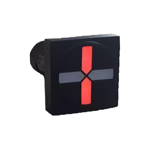
For example, the CPS-501LE model is a square semaphore that is ideal for displaying the four states of a breaker (closed, open, in transit, fault). With standard dimensions and easy installation, these models are suitable replacements for older mechanical and electromechanical indicators.
To view the full range of products, you can visit the Semaphores and Position Indicators page.
Frequently Asked Questions
### What is the main difference between an LED semaphore and a signal lamp?
A signal lamp indicates a single condition (e.g., on or off). A semaphore, however, displays at least two opposing states (like closed/red and open/green) and is used to show the status of a two-state device like a switch.
### Why is DC voltage used in semaphores?
DC voltage, especially in substations, is backed up by batteries and remains stable even if the main grid power is lost. This ensures the reliability of the control and monitoring system.
### What does the fourth state in a four-state semaphore (both LEDs off) mean?
This state usually occurs for two reasons: either the DC supply to the semaphore is cut off (power supply fault), or the switch is in an intermediate position (between open and closed). In either case, it is an abnormal condition that requires operator attention.
### Can I replace old mechanical semaphores with LED ones?
Yes, this is very common and highly recommended. LED semaphores have lower power consumption, a much longer lifespan, higher reliability, and better visibility than mechanical models, and their wiring is similar.
Related Articles
- How Does a Semaphore Display Breaker Status?
- How to Wire an LED Semaphore
- Difference Between LED Semaphore and Signal Lamp