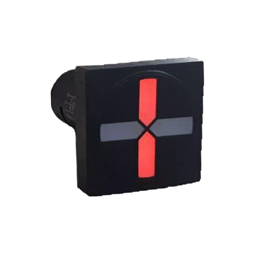
LED Semaphore Wiring Principles
An LED semaphore, or Position Indicator, is an electronic component that displays the status of switching equipment such as breakers, disconnectors, and earth switches on a Mimic Diagram on medium and high voltage switchgear panels. Correctly wiring this device is crucial for an accurate and reliable indication of the equipment's status. The fundamental operation of a semaphore involves receiving a signal from the equipment's auxiliary contacts and converting it into a visual cue (usually red and green LEDs).
The wiring of LED semaphores typically involves three main components:
- **Power Supply:** Usually a DC voltage (e.g., 110 VDC) that provides the necessary energy to light up the LEDs.
- **Status Inputs:** Signals that originate from the equipment's auxiliary contacts.
- **Semaphore Terminals:** Connection points for the power supply and inputs.
Introduction to Terminals and Connection Method
Most standard industrial LED semaphores have three main terminals for displaying two states (like open/closed), commonly labeled X0, X1, and X2.
### Terminals
- **X0 (Common):** The common terminal, which is usually connected to one pole of the power supply (e.g., the positive pole).
- **X1 (Status 1):** The first status input. When a signal reaches this terminal, the LED for the first state (e.g., Close) illuminates.
- **X2 (Status 2):** The second status input. When a signal reaches this terminal, the LED for the second state (e.g., Open) illuminates.
### Sample Wiring Diagram (Connection to a Breaker)
To indicate a circuit breaker's status, we use its auxiliary contacts. These contacts are identified by standard ANSI device numbers:
- **52a:** A Normally Open (NO) contact that closes when the breaker is in the **Closed** position.
- **52b:** A Normally Closed (NC) contact that closes when the breaker is in the **Open** position.
The wiring process is as follows:
1. **Connect Power to Common:** Connect the positive (+) pole of the DC power supply (e.g., 110 VDC) to the semaphore's common terminal (X0).
2. **Connect Other Power Pole to Contacts:** Connect the negative (-) pole of the power supply to the common input of the 52a and 52b auxiliary contacts.
3. **Connect Contact Outputs to Semaphore:**
- Connect the output of the **52a** contact to the semaphore's **X1** terminal (to indicate the Close/Red status).
- Connect the output of the **52b** contact to the semaphore's **X2** terminal (to indicate the Open/Green status).
### Current Path
- **Indicating Close Status (Red):** When the breaker closes, the 52a contact closes, completing the circuit from the negative supply pole, through 52a, to terminal X1. With a positive voltage on X0, the circuit is complete, and the red LED lights up.
- **Indicating Open Status (Green):** When the breaker opens, the 52b contact closes, completing the circuit from the negative supply pole, through 52b, to terminal X2, and the green LED lights up.
- **Invalid (Travel) Status:** While the breaker is changing state, there is a brief moment when both 52a and 52b contacts are open. In this condition, no current flows to X1 or X2, and the semaphore remains off.
Circuit Testing and Common Errors
After completing the wiring, testing the circuit is essential to ensure correct operation.
### Functional Test
- Place the breaker in the Open position. The semaphore should display green.
- Place the breaker in the Closed position. The semaphore should display red.
### Common Errors
| Error | Probable Cause | Solution |
|---|---|---|
| **Reversed Color Indication** | The output wires from the contacts are incorrectly connected to terminals X1 and X2. | Swap the wires connected to X1 and X2. |
| **Semaphore Does Not Light Up** | Power supply is off, a break in the common wire (X0), or the semaphore is burnt out. | Check the supply voltage at the terminals. Test the continuity of the common wire. |
| **Only One Status is Displayed** | A break in the wiring for one of the states or a faulty corresponding auxiliary contact. | Check the wiring path for the contact whose status is not being displayed. |
| **Reversed Supply Polarity** | The positive and negative poles are incorrectly connected to the DC semaphore circuit. | Correct the polarity. Modern semaphores often have reverse polarity protection. |
Rizmooj Electric Toos LED Semaphores
Rizmooj Electric Toos is a manufacturer of high-quality LED semaphores for industrial applications. These products are designed considering the harsh environmental conditions of electrical substations.
Key features of Rizmooj semaphores:
- **Wide Operating Voltage:** Models like the CPS-501LE Square Semaphore operate on a nominal voltage of 110 VDC with a ±50% tolerance, making them resistant to DC voltage fluctuations in substations.
- **Very Low Consumption:** With a current consumption of less than 3 mA, they impose a negligible load on the DC supply system.
- **Design Variety:** They are available in both round (like the EPC-501LE) and square models (like the EPS-501LE) to match different panel designs.
For more information and to see all models, please visit the Position Indicators (Semaphore) product page.
Frequently Asked Questions
### If the semaphore shows the wrong status (green for closed, red for open), what is the problem?
This error is almost always caused by swapping the input wires to the X1 and X2 terminals. Simply interchange these two wires to correct the status indication.
### Why is the semaphore completely off sometimes?
A semaphore being off can have three main reasons: 1) The equipment is in a travel state between open and closed, and both auxiliary contacts are open. 2) The DC power supply is disconnected. 3) The common wire (connected to X0) is broken.
### Can a semaphore also be used to indicate the status of a disconnector?
Yes, the principle is identical. The only difference is that instead of the breaker's auxiliary contacts (52a/52b), the position auxiliary contacts of the disconnector or earth switch are used to send signals to the X1 and X2 terminals.
Related Articles
- What is an LED Semaphore? A Complete Guide to Semaphore Indicators in Switchgear
- What are Terminals X0, X1, and X2 on an LED Semaphore?