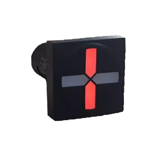
LED Semaphore Selection Guide
Selecting the right semaphore or Position Indicator is a key step in designing control and protection electrical panels. These devices provide operators with vital information about the status of circuit breakers, disconnectors, and other equipment in a visual and easily understandable format. An incorrect choice can lead to misinterpretation of status, delayed response to faults, and compromised safety for personnel and equipment. In this guide, we review the main parameters for selecting a suitable LED semaphore.
### Application Type
The first and most important criterion is the semaphore's application. Will it be used to display the status of a Circuit Breaker, a Disconnector, an Earth Switch, or another device? The application determines the display logic (number of states) and even the semaphore's physical design. For example, a breaker semaphore typically displays "Closed," "Open," "Traveling," and "Fault" states.
### Supply Voltage
Control and protection circuits in substations and power plants often use DC voltage to ensure stable operation during a grid power outage. Common voltages include 24, 48, 110, and 125 VDC. In many regions, **110 VDC** is the dominant standard for high-voltage substations and power plants. The selected semaphore must be compatible with the panel's DC supply voltage. Products with a wide voltage range (such as 110 VDC with a ±50% tolerance) offer greater flexibility against battery bank voltage fluctuations.
### AC/DC
Although AC semaphores exist, the use of **DC** power is a fundamental principle in critical industrial applications and power systems due to its high stability and reliability. The DC supply is provided by batteries and operates independently of the AC grid.
### Display Type and Number of States
Modern LED semaphores can display more than two simple "On" and "Off" states. The most common models are four-state indicators:
- **Closed State:** Usually indicated by a solid red LED.
- **Open State:** Usually indicated by a solid green LED.
- **Traveling State:** When the breaker's main contacts are moving between the open and closed positions. This state may be indicated by both LEDs being off or by them flashing.
- **Fault/Invalid State:** If a problem occurs with the auxiliary contacts or the control circuit, both red and green LEDs might turn on simultaneously to alert the operator of an invalid status.
### Dimensions and Mounting Method
The physical dimensions of the semaphore must match the available space on the panel door and the mimic diagram. The required mounting cutout diameter is a standard parameter. Many semaphores are designed for a standard **22 mm** cutout. The external shape (round or square) is also chosen based on the panel's design.
### Brightness and Viewing Angle
The LEDs used in the semaphore must have sufficient brightness and a wide viewing angle to be clearly visible from various distances and angles within the control room. This is particularly important in environments with bright ambient light.
### Installation Environment
The semaphore should be designed to operate in the environmental conditions of the installation site (e.g., control room, local panel in the switchyard). The IP (Ingress Protection) rating against dust and moisture, as well as resistance to electromagnetic interference (EMI), are important considerations.
### LED Semaphore Selection Checklist
- [ ] **Application:** Breaker, disconnector, or earth switch?
- [ ] **Supply Voltage:** Is it compatible with the panel's DC voltage (e.g., 110V)?
- [ ] **Number of States:** Does it support 2, 3, or 4-state indication?
- [ ] **Dimensions:** Are the body diameter and mounting cutout (e.g., 22 mm) suitable?
- [ ] **Shape:** Round or square?
- [ ] **Brightness:** Is the LED light sufficient for the environment?
- [ ] **Standards:** Does it comply with relevant industry standards?
LED Semaphore Troubleshooting
Even the best semaphores can display the wrong status due to wiring issues or faulty auxiliary contacts. Below, we examine common problems and their troubleshooting methods.
- **Semaphore does not turn on:** First, ensure that the supply voltage is present at the common terminal (usually X0). Then, check for any wire breaks. If the problem persists, the semaphore unit itself may be faulty.
- **Only Red or Only Green does not turn on:** This issue is typically related to the wiring of terminals X1 (for open/green status) and X2 (for closed/red status) or the incorrect operation of the auxiliary contacts (52a/52b for a breaker).
- **Incorrect status display:** If the semaphore shows a reversed status (red for open and green for closed), the wires connected to terminals X1 and X2 have likely been swapped.
- **Testing with a multimeter:** To troubleshoot, measure the voltage between the common terminal (X0) and each of the status terminals (X1 and X2). At any given time, depending on the switch's position, only one of these two terminals should have a voltage relative to X0.
| Fault | Probable Cause | Solution |
|---|---|---|
| Semaphore is completely off | 1. DC supply voltage is off.<br>2. Common terminal (X0) wire is disconnected.<br>3. The semaphore unit has failed. | 1. Check the panel's supply voltage.<br>2. Check the wire connection to terminal X0.<br>3. Replace the semaphore with a new unit. |
| Green (Open) does not light up | 1. The 'open' auxiliary contact (NC or 52b) has not operated.<br>2. Terminal X1 wire is disconnected.<br>3. The green LED has failed. | 1. Check the auxiliary contact's operation.<br>2. Check the wire connection to terminal X1.<br>3. Replace the semaphore unit. |
| Red (Closed) does not light up | 1. The 'closed' auxiliary contact (NO or 52a) has not operated.<br>2. Terminal X2 wire is disconnected.<br>3. The red LED has failed. | 1. Check the auxiliary contact's operation.<br>2. Check the wire connection to terminal X2.<br>3. Replace the semaphore unit. |
| Both colors are on (Fault) | 1. Both auxiliary contacts are closed simultaneously (mechanical fault in the switch).<br>2. Short circuit in the wiring. | 1. Inspect the switch mechanism and auxiliary contacts.<br>2. Check the wiring for terminals X1 and X2. |
| Status is displayed in reverse | The input wires for X1 and X2 are swapped. | Swap the wires connected to terminals X1 and X2. |
What is a Position Indicator?
A **Position Indicator** is a general term for any device that visually displays the position of a mechanical or electrical apparatus.
- **Difference from Semaphore:** "Semaphore" is a specific type of Position Indicator traditionally used to show the status of power switches (open/closed) using standard colors (red/green). Today, the two terms are often used interchangeably.
- **Difference from Signal Lamp:** A Signal Lamp typically indicates a single state (such as voltage presence or a general alarm) and lacks the multi-state logic of a semaphore.
- **Application in Panels:** Semaphores are an integral part of Mimic Diagrams on the front of control panels, allowing operators to assess the overall status of a substation or feeder at a glance.
Recommended Products from Rizmooj Electric Toos
Rizmooj Electric Toos manufactures a wide range of LED semaphores for various applications in the electrical industry. With a nominal voltage of 110 VDC (with high tolerance) and very low current consumption (less than 3 mA), these products are an ideal choice for use in substations and power plants. Models like the CPS-501LE (square for breakers) and SPC-501LE (round for disconnectors), with easy installation in a 22 mm cutout, are designed for compatibility with all types of panels.
You can view all round and square models on the Position Indicators (Semaphore) product page.
Frequently Asked Questions
### What is the main difference between a 2-state and a 4-state semaphore?
A 2-state semaphore only shows the "Closed" (red) and "Open" (green) states. A 4-state semaphore, in addition to these two, can also display a "Traveling" state (in transition) and a "Fault" state (invalid contact status), providing more detailed diagnostic information. All Rizmooj semaphores are four-state.
### Can I replace an old mechanical semaphore with an LED semaphore?
Yes, this is a straightforward replacement. LED semaphores, like Rizmooj's products, operate using the same auxiliary contact signals that activate mechanical or electromechanical semaphores. The main benefits of this upgrade include a much longer lifespan, negligible energy consumption, no maintenance requirements, and the ability to display more states (like fault).
### What is the standard voltage for a semaphore in a substation?
In many countries, the standard voltage for control and protection circuits in transmission and distribution substations is 110 VDC. Therefore, the semaphore must be designed to work with this voltage. A wide operating voltage range is a significant advantage, ensuring the semaphore functions correctly even during battery voltage drops.
Related Articles
- What is an LED Semaphore? A Complete Guide to Semaphore Indicators
- LED Semaphore Troubleshooting