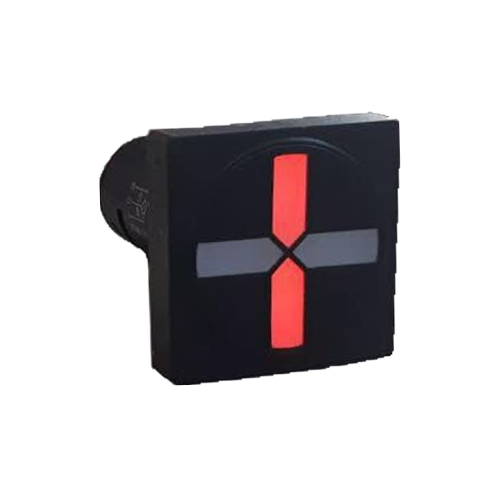
An Introduction to Position Indicators
A Position Indicator is a device that displays the mechanical position of a power switch, disconnector, or earth switch as a clear visual signal for the operator. These devices are typically installed on the door of an electrical panel or on a mimic diagram and use standard colors (usually red for 'ON' and green for 'OFF') to provide vital information about the circuit's status at a glance.
The main difference between a Semaphore and a simple Signal Lamp lies in its operational logic. A signal lamp only shows one state (on or off), whereas an LED semaphore typically indicates at least three or four states:
- **Red (ON):** The switch is in the closed position.
- **Green (OFF):** The switch is in the open position.
- **Off (No Power/Fault):** The DC power supply is disconnected, or there is a problem in the circuit.
- **Red and Green Simultaneously (Error/Travel):** The status is uncertain, the switch is stuck between the open and closed positions, or there is a wiring error.
This capability makes the semaphore a key tool for enhancing safety and speeding up troubleshooting in substations, power plants, and large industrial facilities.
Preliminary Troubleshooting: Checking Common Conditions
When an LED semaphore is not functioning correctly, the first step is to accurately diagnose the displayed state. Common problems usually fall into one of the following categories.
### The Semaphore Does Not Turn On at All
If neither the red nor the green LEDs light up, the most likely cause is a power supply issue.
- **Cause:** Disconnection of the DC supply voltage (typically 110V DC in substation systems) or a break in the common wire (terminal X0).
- **Initial Action:** First, ensure that voltage is present at the power input terminals.
### Only the Red Light (ON State) Does Not Turn On
If the semaphore correctly displays the open state (green) but the red light does not turn on when the breaker is closed, the problem is limited to the 'ON' signal branch.
- **Cause:** A break in the wire connected to terminal X1, a faulty Normally Open (NO) auxiliary contact on the breaker connected to this terminal, or a burnt-out red LED.
- **Initial Action:** Check the X1 wiring path and the operation of the NO contact.
### Only the Green Light (OFF State) Does Not Turn On
This situation is the opposite of the previous problem. The closed state (red) is displayed correctly, but the green light does not turn on when the breaker is opened.
- **Cause:** A break in the wire connected to terminal X2, a faulty Normally Closed (NC) auxiliary contact, or a burnt-out green LED.
- **Initial Action:** Check the X2 wiring path and the operation of the NC contact.
### Both Lights are On or the Status is Incorrect
This is one of the most common issues and is almost always related to incorrect wiring. If the green light turns on when the breaker is closed and vice versa, the X1 and X2 wires have been swapped. If both lights are on simultaneously, the breaker's auxiliary contacts may not be adjusted correctly and are sending signals at the same time.
- **Cause:** Reversed wiring of terminals X1 and X2, or a problem with the mechanical adjustment of the breaker's auxiliary contacts.
- **Initial Action:** Correct the wiring according to the diagram and ensure the auxiliary contacts are functioning properly.
Root Cause Analysis: From Power Supply to Contacts
To permanently resolve the issue, the root cause must be identified.
### DC Power Supply Issues
LED semaphores, like the Rizmooj 501 series, operate on 110V DC. This voltage must be stable and free of significant ripple. Using a multimeter, measure the voltage between the positive polarity of the supply and the semaphore's common wire (X0). The voltage should be within the semaphore's specified tolerance (e.g., 110V DC with a certain tolerance). If there is no voltage, check the fuse or circuit breaker for the DC supply.
### Auxiliary Contact Problems
The semaphore's logic depends on the correct operation of the breaker's auxiliary contacts. These contacts convert the mechanical status of the switch into an electrical signal. An NO contact should only be closed when the breaker is 'ON', and an NC contact should only be closed when the breaker is 'OFF'. Any mechanical defect, wear, or improper adjustment of these contacts will directly affect the semaphore's performance.
### Wire Breaks or Poor Connections
Panel vibrations, heat, and time can cause connections to loosen at the terminals. Carefully inspect the entire wiring path from the breaker's auxiliary contacts to the semaphore's X0, X1, and X2 terminals. Ensure that screws are tight and that there is no corrosion or breakage along the path.
Practical Testing Guide with a Multimeter
For accurate circuit testing, a multimeter is your best tool. (Caution: These tests must be performed by a qualified professional, following all safety procedures.)
1. **Power Supply Test:** Set the multimeter to DC voltage mode. Place the black probe on the negative busbar (Ground) and the red probe on the semaphore's common terminal (X0), which is connected to the positive polarity of the DC supply. You should read the nominal voltage (e.g., 110V).
2. **'ON' Signal Test (Red):** Place the breaker in the closed ('ON') position. Measure the voltage between terminal X1 and ground (negative busbar). You should see the nominal voltage. If the voltage is zero, the problem lies with the NO contact or its wiring.
3. **'OFF' Signal Test (Green):** Place the breaker in the open ('OFF') position. Measure the voltage between terminal X2 and ground (negative busbar). You should see the nominal voltage. If the voltage is zero, the problem lies with the NC contact or its wiring.
4. **Continuity Test:** If you don't get a voltage reading in steps 2 and 3, after completely de-energizing the circuit, you can use the multimeter's continuity test mode to check the integrity of the wires and the contacts themselves.
Quick Troubleshooting Table
| Symptom | Probable Cause | Solution |
|---|---|---|
| Semaphore is completely off | 1. DC power supply is off<br>2. Break in the common wire (X0) | 1. Check the power supply fuse/breaker<br>2. Check the connection of terminal X0 |
| Only the red LED is off | 1. Break in the X1 input wire<br>2. Faulty NO auxiliary contact<br>3. Burnt-out red LED | 1. Check continuity of the X1 wire<br>2. Test the breaker's NO contact<br>3. Replace the semaphore |
| Only the green LED is off | 1. Break in the X2 input wire<br>2. Faulty NC auxiliary contact<br>3. Burnt-out green LED | 1. Check continuity of the X2 wire<br>2. Test the breaker's NC contact<br>3. Replace the semaphore |
| Both LEDs are on | 1. Misaligned auxiliary contacts<br>2. Short circuit between X1 and X2 wires | 1. Adjust the auxiliary contact mechanism<br>2. Inspect wiring for insulation damage |
| Colors are reversed | Incorrect wiring of X1 and X2 inputs | Swap the wires connected to terminals X1 and X2 |
LED Semaphores by Rizmoj Electric Toos
Rizmoj Electric Toos manufactures a wide range of Position Indicators (Semaphores) for various applications in industrial electrical panels, substations, and power plants. Products like the round EPC-501LE and square CPS-501LE models, with a standard operating voltage of 110V DC and very low current consumption (less than 3 mA), provide a reliable solution for displaying the status of power switches and disconnectors. With their four-state indication (red, green, off, and combined), these devices help operators monitor the power system accurately and safely.
Frequently Asked Questions
### Why are both the red and green LEDs on my semaphore lit simultaneously?
This fault usually occurs due to a problem with the switch's auxiliary contacts. The contacts may be improperly adjusted, causing both the NO and NC contacts to be closed at the same time in an intermediate position, thus sending voltage to both X1 and X2 inputs.
### What voltage do Rizmooj semaphores use?
The standard operating voltage for most industrial semaphores, like the Rizmooj 501LE series, is 110V DC. These products have a high voltage tolerance (typically ±50%) to ensure proper operation even under the fluctuating DC voltage conditions found in substations.
### What are the X0, X1, and X2 terminals used for?
This is standard terminology for semaphores: X0 is the common terminal, connected to the positive polarity of the DC power supply. X1 is the signal input for the 'ON' state (red) and is connected to the switch's NO contact. X2 is the signal input for the 'OFF' state (green) and is connected to the switch's NC contact.
### Can I test a semaphore without connecting it to a breaker?
Yes. To test the semaphore itself, connect the positive supply voltage (e.g., +110V DC) to the X0 terminal. Then, by momentarily connecting the negative voltage (ground) to terminal X1, the red LED should light up. Connecting it to terminal X2 should light up the green LED. This test confirms the health of the semaphore unit itself.
Related Articles
- What is an LED Semaphore? A Complete Guide to Semaphore Indicators
- How to Wire an LED Semaphore
- What are the X0, X1, and X2 Terminals on an LED Semaphore?