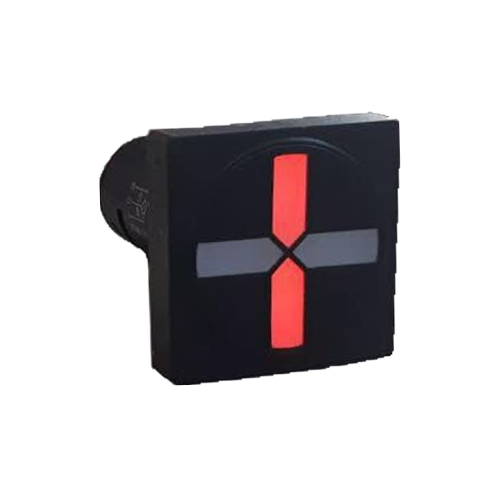
What Are X0, X1 and X2 Terminals in an LED Semaphore?
In electrical panels, high-voltage substations, and power plants, accurately displaying the status of switchgear is critical. LED semaphores, or Position Indicators, are standard devices for this purpose. Using colored LEDs (usually red and green), these devices show operators whether breakers, disconnectors, or earth switches are in the Open or Closed position. For correct operation, these semaphores must be properly connected to the equipment's auxiliary contacts. The three main terminals for this connection are X0, X1, and X2, and understanding their function is fundamental to semaphore wiring.
### Introduction to X0 (Common Terminal)
The X0 terminal acts as the common terminal. In most applications, this terminal is connected to one pole of the DC power supply (e.g., the positive pole). X0's function is to provide a reference point for the semaphore's internal circuitry, and current is supplied through this pin to light up the LEDs.
### Introduction to X1 (First State Terminal)
The X1 terminal is the input for the first state. This state is typically assigned to the "Closed" position and is indicated by the **red** color. To activate this state, the X1 terminal must be connected to the other pole of the power supply (e.g., the negative pole). This connection is made through an auxiliary contact from the main equipment (such as a breaker's 52a contact).
### Introduction to X2 (Second State Terminal)
The X2 terminal is the input for the second state. This state is usually assigned to the "Open" position and is indicated by the **green** color. Similar to X1, to activate this state, the X2 terminal must be connected to the negative pole of the power supply through another auxiliary contact (such as a breaker's 52b contact).
Current Path and Status Indication
To better understand, let's assume we have an LED semaphore, like the Rizmooj 501 series models, with a supply voltage of 110 VDC. The standard wiring is as follows:
- **X0 Terminal**: Connected to the positive (+) pole of the 110 VDC power supply.
- **X1 Terminal**: Connected to the negative (-) pole of the power supply via the breaker's normally open (NO - 52a) auxiliary contact.
- **X2 Terminal**: Connected to the negative (-) pole of the power supply via the breaker's normally closed (NC - 52b) auxiliary contact.
### Closed Status Indication (Red)
When the breaker is in the **Closed** position:
1. The 52a contact (normally open) closes.
2. The 52b contact (normally closed) opens.
3. A current path is created from the positive pole, through the X0 terminal, the internal red LED circuit of the semaphore, the X1 terminal, the closed 52a contact, and finally to the negative pole.
4. As a result, the semaphore turns **red**, indicating the breaker is closed.
### Open Status Indication (Green)
When the breaker is in the **Open** position:
1. The 52a contact returns to its initial state (open).
2. The 52b contact returns to its initial state (closed).
3. A current path is created from the positive pole, through the X0 terminal, the internal green LED circuit of the semaphore, the X2 terminal, the closed 52b contact, and finally to the negative pole.
4. As a result, the semaphore turns **green**, indicating the breaker is open.
### Sample Wiring Diagram
A simple diagram would include a DC power source, the semaphore with its X0, X1, and X2 terminals, and the breaker's 52a and 52b auxiliary contacts. This diagram clearly shows how the mechanical state of the breaker is translated into an electrical signal for the semaphore.
### Testing with a Multimeter
You can use a multimeter for troubleshooting:
- **Voltage Test**: Set the voltmeter to DC mode. When the breaker is closed, the voltage between X0 and X1 should be approximately the supply voltage (e.g., 110V), and zero between X0 and X2. This condition is reversed when the breaker is open.
- **Continuity Test**: With the power off, you can measure the resistance between terminals X1 and X2 to ground (the negative pole) to verify the correct operation of the 52a and 52b contacts.
### Common Wiring Errors
| Error | Result | Solution |
|---|---|---|
| Swapping X1 and X2 | Colors are reversed (red for open, green for closed). | Swap the wires connected to X1 and X2. |
| Connecting X0 to the negative pole | Semaphore does not turn on (unless X1/X2 are wired to positive). | Correct the polarity of the power supply connected to X0. |
| Open circuit in the X0 wire | Semaphore does not turn on in any state. | Check and fix the connection of the common wire (X0). |
| Faulty 52a or 52b contact | One or both colors fail to light up. | Check the breaker's auxiliary contacts and repair or replace if necessary. |
Application in Disconnectors and Earth Switches
These principles apply equally to disconnectors and earth switches. These devices also have auxiliary contacts to indicate their open or closed status. A semaphore connected to a disconnector displays its status on the panel's Mimic Diagram, which is crucial for safety interlocks. For example, an operator must ensure the disconnector is open (by seeing its green semaphore) before closing the corresponding earth switch.
Choosing the Right Semaphore
When selecting an LED semaphore, factors such as supply voltage (which must match the substation's DC voltage), dimensions, and display type (round or square) should be considered. Rizmooj Electric Toos products, such as the **EPC-501LE** (round) and **EPS-501LE** (square) models, are reliable options for industrial panels and substations, featuring a nominal voltage of 110 VDC and very low current consumption (less than 3 mA).
Frequently Asked Questions
### What happens if both 52a and 52b contacts are closed simultaneously?
This indicates a mechanical fault in the breaker, known as an invalid state. In this case, both X1 and X2 inputs are activated. Depending on the semaphore's design, it might light up both LEDs, none of them, or a specific color as a warning to alert the operator to the fault.
### Can AC voltage be used to power LED semaphores?
No, most standard industrial semaphores, like Rizmooj models, are designed to operate on DC voltage. Applying AC voltage can cause serious damage to their internal circuitry. Always check the product's technical specifications before making connections.
### Why is a common terminal (X0) used?
Using a common terminal simplifies wiring and makes it more economical. Instead of needing four wires (two for each LED), only three are required, reducing the amount of wiring inside the panel.
Related Articles
- How to Wire an LED Semaphore
- How a Semaphore Indicates Breaker Status
- LED Semaphore Troubleshooting
- What Are NO and NC Contacts?
- LED Semaphore Selection Guide
To see and review a variety of industrial LED semaphores, visit the Position Indicator products page of Rizmooj Electric Toos.