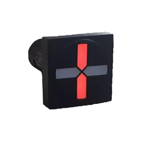
Application of Semaphores in Disconnectors and Earth Switches
In power systems, accurate and real-time indication of switching equipment status is essential for safe and correct operation. Semaphores, or Position Indicators, are a key tool for this purpose, especially for equipment like disconnectors and earth switches that are directly related to personnel and equipment safety.
- **Disconnector:** A mechanical switch used to connect or disconnect a circuit under no-load conditions. Its primary purpose is to create a visible, physical isolation gap in the circuit for maintenance. The "Close" or "Open" status of the disconnector must be clearly visible to the operator.
- **Earth Switch:** A switch used to connect a part of the circuit to the ground to discharge any residual electrical charges and ensure it is de-energized during maintenance. Its status determines whether it is safe or dangerous to work on the equipment.
To display the status of these switches on control panels, their auxiliary contacts (Position Contacts) are used. These contacts are coupled with the main mechanism of the switch and send an electrical signal to the semaphore corresponding to the open or closed state. The semaphore then converts this signal into a visual display (usually red for closed and green for open). This system, along with mechanical and electrical interlocks, prevents human error and incorrect equipment operation.
Difference Between LED, Mechanical, and Electromechanical Semaphores
Over time, semaphores have been manufactured with various technologies, each with its own advantages and disadvantages.
- **Mechanical Semaphore:** The oldest type, which indicates status by the physical movement of a colored flag or indicator. This type is usually directly connected to the switch mechanism and requires no electrical power, but its drawbacks include slow operation, high wear and tear, and the inability to be used over long distances.
- **Electromechanical Semaphore:** In this model, an electrical signal activates a small relay or coil, causing a physical indicator to move. It is more advanced than the mechanical type but still has moving parts, a limited lifespan, and relatively high energy consumption.
- **LED Semaphore:** The most modern and widely used type of semaphore. This model uses light-emitting diodes (LEDs) to display status. The absence of moving parts results in a very long life (over 100,000 hours), instantaneous operation, extremely low power consumption (a few milliamperes), and high reliability. They also have high readability in various lighting conditions and are virtually maintenance-free.
### Semaphore Types Comparison Table
| Feature | LED Semaphore | Electromechanical Semaphore | Mechanical Semaphore |
|---|---|---|---|
| Structure | Solid-State | Coil and Lever | Purely Mechanical |
| Operating Speed | Instantaneous | Milliseconds | Depends on switch speed |
| Lifespan | Very High (>100,000 hrs) | Medium (moving parts) | Low (wear and tear) |
| Power Consumption | Very Low (few mA) | Low to Medium | Zero (no power needed) |
| Maintenance | Virtually Zero | Requires periodic inspection | Requires lubrication & adjustment |
| Readability | Excellent at wide angles | Good | Moderate |
| Suitable Application | Modern systems, control panels | Older systems | Direct mounting on equipment |
Difference Between LED Semaphore and Signal Lamp
Although both are used for visual indication on electrical panels, their application and the type of information they convey are completely different.
- **Signal Lamp:** A single-state indicator. It only shows one condition; for example, being on means "Fault" or "Motor On." These lamps are typically used for warnings, alarms, or confirming a specific state.
- **Semaphore Indicator:** A multi-state indicator (usually two-state or four-state) that shows the *position* of a device. For example, for a disconnector, it displays the "Closed" (red) and "Open" (green) states. A semaphore specifies the status of a two-position switch rather than announcing an event.
### Semaphore vs. Signal Lamp Comparison Table
| Feature | LED Semaphore | Signal Lamp |
|---|---|---|
| Information Type | Position/Status | Event/Alarm |
| Display Type | Multi-state (Red/Green) | Single-state (On/Off) |
| Primary Use | Indicates breaker, disconnector status | Indicates fault, alarm, power status |
| Wiring | Minimum three wires (Common, Open signal, Close signal) | Two wires (Phase & Neutral or +/-) |
The Meaning of Red and Green Colors in a Semaphore
Color selection in semaphores follows industry standards to prevent misinterpretation. In the power industry, especially for power switches:
- **Red:** Means **Closed**. This color indicates that the circuit is closed and energized, which is considered a **dangerous** condition.
- **Green:** Means **Open**. This color indicates that the circuit is open, isolated, and de-energized, signifying a **safe** condition for work.
This convention is contrary to the common understanding from traffic lights and can sometimes confuse non-specialists. In four-state semaphores, other states may also be defined:
- **Both colors off:** Indicates that the semaphore or control circuit power supply is off.
- **Both colors on simultaneously:** Usually defined as a **Fault** condition or an indeterminate state (between open and closed).
One should always refer to the project documentation and diagrams, as in rare cases, a client may request a different color convention. Standards like IEC 60073 provide general guidelines in this area.
How is a Semaphore Used in a Mimic Diagram?
A single-line diagram or Mimic Diagram (Mimic Bus) is a schematic map of the power system installed on the front of control panels or in control rooms. This diagram helps operators quickly understand the network structure and the status of major equipment.
Semaphores are an integral part of these diagrams. They are placed exactly at the schematic representation of equipment like breakers, disconnectors, and earth switches. When a disconnector in the actual substation is opened, its auxiliary contact sends a signal to the corresponding semaphore on the mimic diagram, and the semaphore turns green. This direct link between the real equipment status and the graphical display makes system monitoring very simple and intuitive.
Guide to Selecting an LED Semaphore
To choose a suitable LED semaphore, several key parameters must be considered:
- **Supply Voltage:** Check the control circuit voltage. In substations, 110 VDC is very common. Products like Rizmooj's `SPC-501LE` and `CPS-501LE` series semaphores are designed for this standard voltage.
- **Display Type:** Do you need a two-state display (open/closed) or a four-state display (open, closed, fault, no supply)?
- **Dimensions and Mounting:** Specify the panel cutout diameter (usually 22mm or 30mm) and the shape (round or square). Models like the EPC-501LE (round) and EPS-501LE (square) offer various options.
- **Brightness and Viewing Angle:** The semaphore must be clearly visible from various angles and in ambient light conditions.
- **Installation Environment:** The Ingress Protection (IP) rating of the semaphore must be compatible with the environmental conditions (dust, moisture).
Troubleshooting LED Semaphores
Problems with LED semaphores are usually not related to the units themselves but rather to the auxiliary circuits.
| Fault | Possible Cause | Solution |
|---|---|---|
| Semaphore is completely off | Supply voltage (e.g., 110 VDC) is off | Check the voltage on the common terminal (X0) with a multimeter. Check the control circuit fuse. |
| Only one state (e.g., green) works | Break in the wiring for the other state (red) | Check the wiring of the corresponding terminal (e.g., X1 for red) to the auxiliary contact. |
| Displays the wrong status | Incorrect wiring of X1 and X2 terminals | Swap the wires connected to the open and close status terminals. |
| Both colors are on simultaneously (fault) | The switch's auxiliary contact is stuck in an intermediate position, or both NO and NC contacts are closed. | Inspect and adjust the switch mechanism and its auxiliary contacts. |
### Recommended Rizmooj Products
Rizmooj Electric Toos produces a wide range of LED semaphores for industrial applications. Models like the SPC-501LE and CPS-501LE are specifically designed to indicate the status of disconnectors and breakers with the standard 110 VDC voltage. Their high quality and reliability make them an ideal choice for substations and control panels.
To see all models, visit the Position Indicators and Semaphores page.
Frequently Asked Questions
### Why not use two separate signal lamps to show open and closed states?
Using an integrated semaphore simplifies wiring (one common terminal), occupies less space on the panel, and visually represents the relationship between the open and closed states better. It also allows for displaying fault conditions (both on) or power loss (both off), which is not possible with two separate lamps.
### Can a semaphore also be used to indicate a circuit breaker's status?
Yes, semaphores are widely used to indicate the status of circuit breakers as well. The color convention is the same: red for closed and green for open. Models like the square semaphore CPS-501LE are specifically designed for this application.
### What is the operating voltage of LED semaphores?
Semaphores are produced with various AC and DC voltages. In substation and power plant applications, DC voltage (such as 24, 48, or 110 VDC) is preferred due to the presence of battery banks and higher reliability. Most Rizmooj semaphores operate on the industrial standard 110 VDC (with high tolerance).
Related Articles
- What is an LED Semaphore? A Complete Guide to Semaphore Indicators in Electrical Panels
- Difference Between LED, Mechanical, and Electromechanical Semaphores
- What Do Red and Green Mean in a Semaphore?